
DIE SINKS – DIE & MOLD END MILLS
FEATURES & BENEFITS
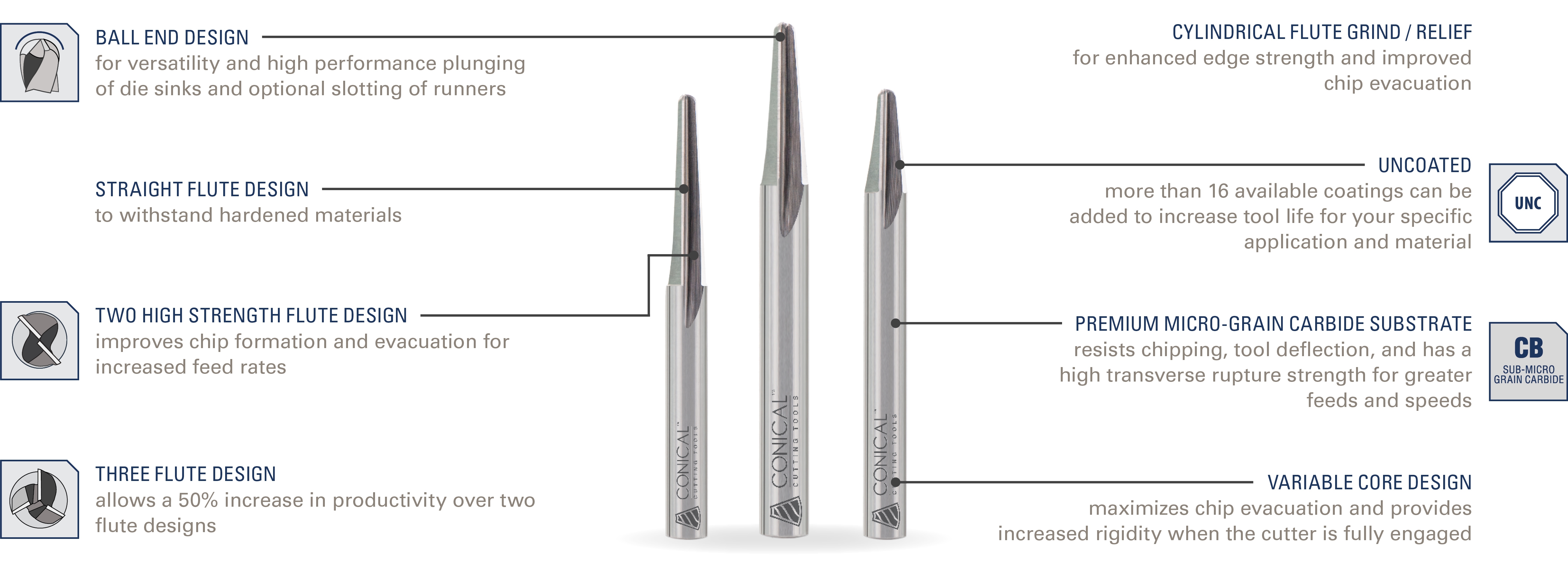
Global Die Sinks have a versatile design to be used in multiple processes of die and mold manufacturing. They have the versatility to plunge, taper existing holes, machine runners and act as a burr removal tool whenever necessary. The Global way is to go above and beyond current standards in the market, whenever possible. That’s why you will find the Global Die Sink end mill with a larger core, high strength flute design, and premium micro-grain carbide, which maintains all our products as the last word in value.
RESULTS
The neutral rake angle provides superior chip evacuation and protects the tool edge when machining difficult materials. Whether plunging, slotting or making runners in hardened material, the Global Die Sink performs amazingly well, as a result of our advanced engineering. When ferrous material and aluminum are on the machine, this will be your tool of choice. The two flute design clears chips quickly and leaves the finished product for your approval.
| CARBIDE DIE SINK END MILLS | |||||||||||||
|---|---|---|---|---|---|---|---|---|---|---|---|---|---|
| ANGLE | DIAMETER | LENGTH | # OF FLUTES | ALTIN COATED | |||||||||
| PER SIDE | INCLUDED | TIP SIZE | LARGE END | SHANK | OF CUT | OVERALL | |||||||
| A | +0°30′ | D2 | +.002″ | D3 | D1 | L2 | +.100″ | L1 | PART # | EDP# | |||
| -0°30′ | -.002″ | -.000″ | |||||||||||
| 3° | 6° | 0.0313 | – | 1/8 | 0.125 | 0.875 | 2.000 | 2 | DS2-C0001 | – | |||
| 3° | 6° | 0.0625 | – | 1/8 | 0.125 | 0.563 | 2.000 | 2 | DS2-C001 | – | |||
| 3° | 6° | 0.0625 | – | 3/16 | 0.188 | 1.000 | 2.000 | 2 | DS2-C002 | – | |||
| 3° | 6° | 0.0625 | – | 1/4 | 0.250 | 1.500 | 2.500 | 2 | DS2-C003 | – | |||
| 3° | 6° | 0.1250 | – | 1/4 | 0.250 | 1.000 | 2.500 | 2 | DS2-C201 | – | |||
| 3° | 6° | 0.0313 | – | 1/8 | 0.125 | 0.875 | 2.000 | 3 | DS3-C0001 | – | |||
| 3° | 6° | 0.0625 | – | 1/8 | 0.125 | 0.563 | 2.000 | 3 | DS3-C001 | – | |||
| 3° | 6° | 0.0625 | – | 3/16 | 0.188 | 1.000 | 2.000 | 3 | DS3-C002 | – | |||
| 3° | 6° | 0.0625 | – | 1/4 | 0.250 | 1.500 | 2.500 | 3 | DS3-C003 | – | |||
| 3° | 6° | 0.1250 | – | 1/4 | 0.250 | 1.000 | 2.500 | 3 | DS3-C201 | – | |||
| 5° | 10° | 0.0313 | – | 1/8 | 0.125 | 0.500 | 2.000 | 2 | DS2-E0001 | – | |||
| 5° | 10° | 0.0625 | – | 1/8 | 0.125 | 0.375 | 2.000 | 2 | DS2-E001 | – | |||
| 5° | 10° | 0.0625 | – | 3/16 | 0.188 | 0.688 | 2.000 | 2 | DS2-E002 | – | |||
| 5° | 10° | 0.0625 | – | 1/4 | 0.250 | 1.063 | 2.500 | 2 | DS2-E003 | – | |||
| 5° | 10° | 0.1250 | – | 1/4 | 0.250 | 0.688 | 2.500 | 2 | DS2-E201 | – | |||
| 5° | 10° | 0.0313 | – | 1/8 | 0.125 | 0.500 | 2.000 | 3 | DS3-E0001 | – | |||
| 5° | 10° | 0.0625 | – | 1/8 | 0.125 | 0.375 | 2.000 | 3 | DS3-E001 | – | |||
| 5° | 10° | 0.0625 | – | 0.188 | 0.688 | 2.000 | 3 | DS3-E002 | – | ||||
| 5° | 10° | 0.0625 | – | 1/4 | 0.250 | 1.063 | 2.500 | 3 | DS3-E003 | – | |||
| 5° | 10° | 0.1250 | – | 1/4 | 0.250 | 0.688 | 2.500 | 3 | DS3-E201 | – | |||
| 7° | 14° | 0.0313 | – | 1/8 | 0.125 | 0.375 | 2.000 | 2 | DS2-G0001 | – | |||
| 7° | 14° | 0.0625 | – | 1/8 | 0.125 | 0.250 | 2.000 | 2 | DS2-G001 | – | |||
| 7° | 14° | 0.0625 | – | 3/16 | 0.188 | 0.500 | 2.000 | 2 | DS2-G002 | – | |||
| 7° | 14° | 0.0625 | – | 1/4 | 0.250 | 0.750 | 2.500 | 2 | DS2-G003 | – | |||
| 7° | 14° | 0.0938 | – | 3/16 | 0.188 | 0.375 | 2.000 | 2 | DS2-G101 | – | |||
| 7° | 14° | 0.1250 | – | 1/4 | 0.250 | 0.500 | 2.500 | 2 | DS2-G201 | – | |||
| 7° | 14° | 0.1875 | – | 3/8 | 0.375 | 0.750 | 2.500 | 2 | DS2-G301 | – | |||
| 7° | 14° | 0.2500 | – | 1/2 | 0.500 | 1.000 | 3.000 | 2 | DS2-G401 | – | |||
| 7° | 14° | 0.0313 | – | 1/8 | 0.125 | 0.375 | 2.000 | 3 | DS3-G0001 | – | |||
| 7° | 14° | 0.0625 | – | 1/8 | 0.125 | 0.250 | 2.000 | 3 | DS3-G001 | – | |||
| 7° | 14° | 0.0625 | – | 3/16 | 0.188 | 0.500 | 2.000 | 3 | DS3-G002 | – | |||
| 7° | 14° | 0.0625 | – | 1/4 | 0.250 | 0.750 | 2.500 | 3 | DS3-G003 | – | |||
| 7° | 14° | 0.0938 | – | 3/16 | 0.188 | 0.375 | 2.000 | 3 | DS3-G101 | – | |||
| 7° | 14° | 0.1250 | – | 1/4 | 0.250 | 0.500 | 2.500 | 3 | DS3-G201 | – | |||
| 7° | 14° | 0.1875 | – | 3/8 | 0.375 | 0.750 | 2.500 | 3 | DS3-G301 | – | |||
| 7° | 14° | 0.2500 | – | 1/2 | 0.500 | 1.000 | 3.000 | 3 | DS3-G404 | – | |||
PRODUCTION ENHANCEMENTSProper tool setup and selection can improve your running parts by nearly 3 fold. Rather than using a 7 multi-axis machine and substantial programming time to cut a draft angle, the use of our tapered end mills were able to improve the finish and dramatically increase production results.
